Getting Started
Introduction

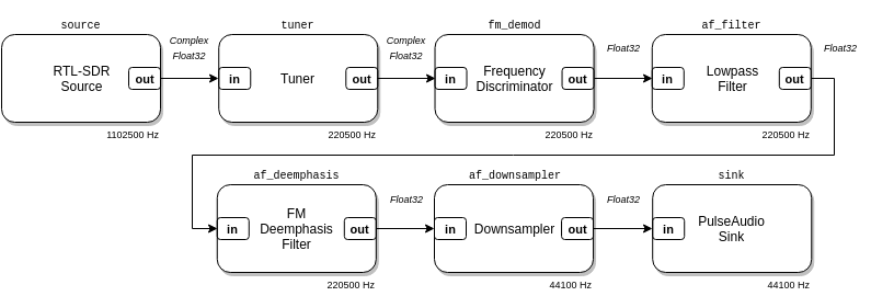
LuaRadio is a framework for building signal processing flow graphs. A flow graph is a directed graph of blocks that processes data samples. Samples in a flow graph originate at source blocks, are manipulated through intermediate processing blocks, and terminate at sink blocks. This paradigm — also called dataflow programming — is useful for software-defined radio, because it allows you to model the architectures of conventional hardware radios.
In a software-defined radio flow graph, source and sink blocks tend to implement some kind of I/O, like reading samples from an SDR dongle, or writing samples to an IQ file, while processing blocks tend to be computational, like filters and multipliers.
Type Signatures

LuaRadio blocks have data types associated with their input and output ports.
For example, a multiplier block may support complex-valued inputs named in1
and in2, with a complex-valued output named out. It may also support
real-valued inputs named in1 and in2, with a real-valued output named
out. Each collection of data types associated with the input and output
ports is called a type signature.

LuaRadio chooses the correct type signature for each block in a flow graph, so that output and input types match in the connections between blocks.
Sample Rate

LuaRadio blocks have a sample rate associated with them. This is the rate at which the discrete samples are spaced in time, relative to one another, but not the rate that they are computationally produced, processed, or consumed by the framework. Source blocks define their sample rates, while downstream blocks inherit — and possibly modify — the sample rate of their upstream block. For example, interpolator and decimator blocks will multiply and divide the sample rate, respectively.
LuaRadio propagates sample rates between blocks for you, and ensures that sample rates match across multiple inputs. Blocks can access their runtime sample rate to perform sample rate dependent initialization and computations.
Flow Graph Termination

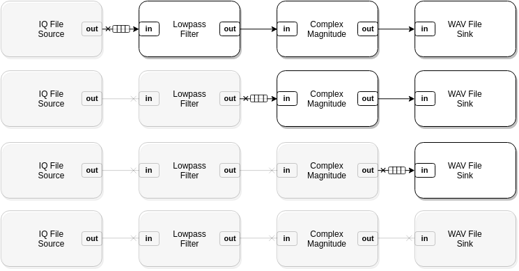
While some flow graphs may describe a continuously running system (e.g. a Wideband FM broadcast radio receiver), LuaRadio flow graphs do not necessarily run forever. If a source terminates, the framework will gracefully collapse the flow graph as the final samples propagate their way though the graph. This allows you to build utilities with LuaRadio that process files to completion, or to use it as an engine for processing finite length data.
Example
In this example, we will create a simple flow graph to mix two cosine signals. It will demonstrate the basic mechanics of instantiating blocks, connecting blocks, and running a flow graph.

local radio = require('radio')

-- Blocks
local source1 = radio.SignalSource('cosine', 125e3, 1e6) -- 125 kHz cosine source, sampled at 1 MHz
local source2 = radio.SignalSource('cosine', 75e3, 1e6)  -- 75 kHz cosine source, sampled at 1 MHz
local mixer = radio.MultiplyBlock()                      -- Multiply block
local throttle = radio.ThrottleBlock()                   -- Throttle block
local sink = radio.GnuplotSpectrumSink()                 -- Spectrum plotting sink
local top = radio.CompositeBlock()                       -- Top-level block to contain the flow graph

-- Connections
top:connect(source1, 'out', mixer, 'in1')
top:connect(source2, 'out', mixer, 'in2')
top:connect(mixer, throttle, sink)

-- Run it
top:run()
Run the flow graph with the luaradio runner:
$ ./luaradio test.lua
The flow graph can be terminated with Ctrl-C or SIGINT.
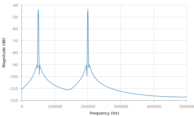
This flow graph mixes two tones at 125 kHz and 75 kHz to create the sum and difference frequency tones at 200 kHz and 50 kHz, respectively.
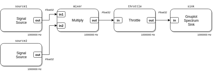
The two sources produce real-valued sinusoids at 125 kHz and 75 kHz and are connected to the inputs of the multiplier. The output of the multiplier is connected to a throttle block, which artificially throttles processing to limit CPU usage. The throttle block is connected to a gnuplot spectrum sink, which plots the frequency spectrum of the signal with gnuplot. This flow graph produces the plot below:

Explanation
local radio = require('radio')
The first line of the example imports the radio package under the local
variable radio. This package exposes all LuaRadio blocks, as well the
facilities to create custom blocks and types.
-- Blocks
local source1 = radio.SignalSource('cosine', 125e3, 1e6) -- 125 kHz cosine source, sampled at 1 MHz
local source2 = radio.SignalSource('cosine', 75e3, 1e6)  -- 75 kHz cosine source, sampled at 1 MHz
local mixer = radio.MultiplyBlock()                      -- Multiply block
local throttle = radio.ThrottleBlock()                   -- Throttle block
local sink = radio.GnuplotSpectrumSink()                 -- Spectrum plotting sink
local top = radio.CompositeBlock()                       -- Top-level block to contain the flow graph
The blocks section lines instantiate each block of the flow graph. Note that sample rate parameters are only required for the source blocks; all other blocks inherit their sample rate through the connections in the flow graph.
The last line of the blocks section instantiates a special kind of block,
called the CompositeBlock. A
composite block is a composition of blocks, created for one of two purposes:
either for a top-level block — a composition of blocks forming a complete flow
graph that can be run, or for a hierarchical block — a composition of blocks
abstracted into one block. In this example, we create a CompositeBlock to
serve as a top-level block that contains a complete flow graph.
-- Connections
top:connect(source1, 'out', mixer, 'in1')
top:connect(source2, 'out', mixer, 'in2')
top:connect(mixer, throttle, sink)
The connections section lines specify the connections between blocks, inside the top-level block, which form the complete flow graph.
The first two connections demonstrate the explicit connection syntax. For
instance, top:connect(source1, 'out', mixer, 'in1'), where source1’s output
port named out is explicitly connected the mixer’s input port named in1.
In this case, the mixer has two inputs, in1 and in2, so we use the explicit
connection syntax to specify which input the source block output should connect
to.
The third connection demonstrates the linear block connection syntax. This
syntax will take any number of blocks, e.g. top:connect(b1, b2, b3, ...),
and connect the first output to the first input of each adjacent block. This
syntax is convenient for connecting chains of blocks that only have one input
and output, which is most blocks.
-- Run it
top:run()
The last line of the example runs the flow graph. This line will block until
the flow graph terminates, either naturally by an exiting source, or forcibly
by a user’s SIGINT signal. In this case, the cosine signal generator sources
will generate samples indefinitely, so this flow graph will only terminate by a
user’s SIGINT signal.
Blocks and Types
Building flow graphs with LuaRadio is a matter of choosing the right blocks and connecting them. The LuaRadio Reference Manual documents all packaged blocks, including a description of their operation, their arguments, and their input/output port names and data types. Creating blocks is easy, too, and covered in the next guide, Creating Blocks.
LuaRadio blocks may support multiple type signatures for their input and output ports, but only blocks with compatible output and input types can be connected. When LuaRadio initializes a flow graph, it differentiates each block based on its input data types to the correct type signature. LuaRadio will raise an error if a block does not support a type signature that matches its input data types.
LuaRadio comes with four basic data types:
ComplexFloat32, compatible with thefloat complexC typeFloat32, compatible with thefloatC typeByte, compatible with theuint8_tC typeBit, compatible with theuint8_tC type, stored in the least significant bit
Under the hood, the framework moves vectors of contiguous samples between blocks for processing. Since these vectors are simply dynamic arrays of C types, LuaRadio blocks can leverage the LuaJIT foreign function interface (FFI) to call external libraries to process them.
In addition, users may create custom data types based on C structures or Lua objects that are serializable between processing blocks. See the Custom Types section of the next guide.
Caveats
The LuaRadio architecture has a few important caveats.
Flow graphs must be acyclic.
Feedback loops cannot be implemented by blocks connected in a cycle. Instead,
operations that require feedback loops must be implemented entirely within a
block (for example, the PLLBlock).
Blocks cannot be manipulated after a flow graph is running.
Blocks must get all of the settings they need before they are run in a flow graph. This means that building flow graphs that require runtime modifications to blocks — for example, programmatically retuning the frequency of an SDR source to build a spectrum analyzer — is not possible without creating a custom block that accepts the runtime modifications via out-of-band messaging.
Next Steps…
The next guide, Creating Blocks, describes the basic concepts behind blocks, data types, and vectors, and demonstrates how to create blocks and data types.